The Line, Not Just the Part
Every other blueprint on this site schedules a single build — one solar plant, one rocket, one research program. This one schedules a line: the tooling, machine qualification, pilot build, first article inspection, and volume ramp for the VR-40 Integrated Actuator, the rotary joint actuator that powers every arm, leg, and torso joint on Vantage Robotics’ Aegis humanoid platform. A humanoid robot needs 30 to 40 of these actuators per unit, and the actual scheduling problem is never “build one” — it is “stand up a repeatable process that can build them by the hundred without a first-pass yield collapse.”
That shape of problem — tooling, then a pilot batch, then a staffed-up steady-state line — is also why this blueprint uses a build technique none of the others do: a CSV/Excel import instead of a pasted tagged text block or an AI prompt sequence. A manufacturing engineering team standing up a new line almost always already has the task list somewhere — an ERP router, a program management spreadsheet, an MRP export — as a flat table of rows and columns, not as a hand-typed tag syntax. Two spreadsheets, imported in the right order, are what this schedule actually looks like before anyone opens Maverick.
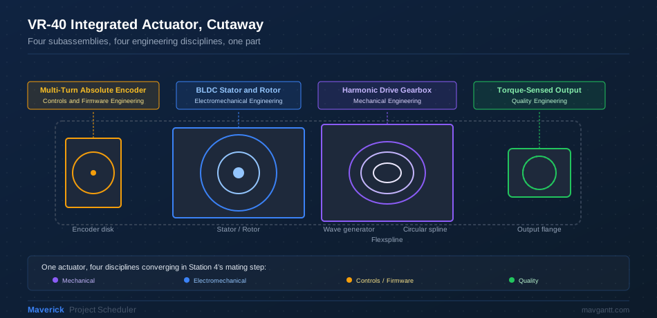
The VR-40 itself is a compact case study in why this line needs four different engineering disciplines to agree on one schedule. Mechanical engineering owns the harmonic drive gearbox. Electromechanical engineering owns the BLDC motor and encoder. Controls and firmware engineering own the torque-control loop that makes the joint safe to put a hand near. Quality engineering owns the gate that decides whether any of it ships. This blueprint schedules all four in one line, one program, one pair of CSV files.
Program at a Glance
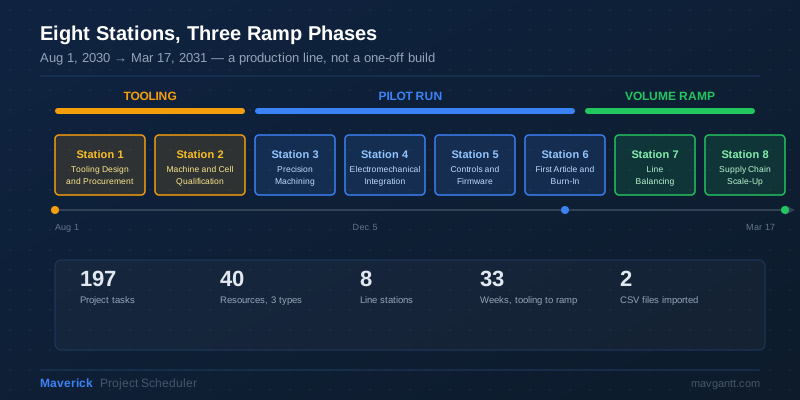
Before the first CSV is imported, here is the shape of what it builds: eight stations grouped into three ramp phases, running from tooling procurement in August 2030 through steady-state volume production in March 2031.
Skills by Discipline
What each engineering function on the line actually practices in this blueprint.
| Discipline | What You’ll Practice |
|---|---|
| Mechanical Engineering | Harmonic drive gearbox tooling, precision machining sequencing, and tolerance stack-up as scheduled work, not just drawings |
| Electromechanical Engineering | Motor and encoder subassembly builds converging into a single mating step via a Finish-to-Finish link |
| Controls and Firmware Engineering | Torque-loop bring-up scheduled to start before hardware integration finishes, using a Start-to-Start link with lag |
| Quality Engineering | First article inspection and burn-in as explicit schedule gates, not informal sign-offs |
| Program and Manufacturing Management | Bulk resource and task import, dependency verification, baseline, critical path, and resource-centric Gantt review across all 197 tasks |
Station 1: Import the Resource Pool First
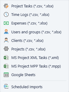
Go to File → Import → Users and groups. This is the single most important sequencing rule in this blueprint: import the Users CSV before the Project Tasks CSV. The task import assigns resources by name, and a name resolves only if the resource already exists — import tasks first and every Users cell in that file silently fails to assign.
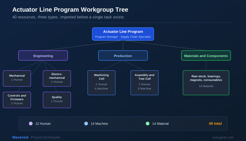
The Users CSV force-creates 40 resources under a nested workgroup tree — 12 Human, 14 Machine, and 14 Material — split across Engineering, Production, and Materials and Components. The Parent group column uses the same colon-delimited path convention as the workgroup paths used elsewhere on the site, so Actuator Line Program:Engineering:Controls and Firmware Engineering creates a three-level nested group in one row.
| Name | Parent group | Resource type |
|---|---|---|
| Program Manager | Actuator Line Program | 0 |
| Mechanical Design Engineer | Actuator Line Program:Engineering:Mechanical Engineering | 0 |
| Manufacturing Engineer | Actuator Line Program:Production | 0 |
| Electromechanical Engineer | Actuator Line Program:Engineering:Electromechanical Engineering | 0 |
| Controls Engineer | Actuator Line Program:Engineering:Controls and Firmware Engineering | 0 |
| Firmware Engineer | Actuator Line Program:Engineering:Controls and Firmware Engineering | 0 |
| Quality Engineer | Actuator Line Program:Engineering:Quality Engineering | 0 |
| CNC Machinist | Actuator Line Program:Production:Machining Cell | 0 |
| Assembly Technician | Actuator Line Program:Production:Assembly and Test Cell | 0 |
| Test Technician | Actuator Line Program:Production:Assembly and Test Cell | 0 |
| Supply Chain Specialist | Actuator Line Program:Production | 0 |
| Production Line Supervisor | Actuator Line Program:Production | 0 |
| 5-Axis CNC Mill | Actuator Line Program:Production:Machining Cell | 2 |
| CNC Gear Hobbing Machine | Actuator Line Program:Production:Machining Cell | 2 |
| Wire EDM Machine | Actuator Line Program:Production:Machining Cell | 2 |
| Precision Cylindrical Grinder | Actuator Line Program:Production:Machining Cell | 2 |
| Heat-Treat Furnace | Actuator Line Program:Production:Machining Cell | 2 |
| Ultrasonic Cleaning System | Actuator Line Program:Production:Machining Cell | 2 |
| Automated Stator Winding Machine | Actuator Line Program:Production:Assembly and Test Cell | 2 |
| Robotic Pick-and-Place Cell | Actuator Line Program:Production:Assembly and Test Cell | 2 |
| Coordinate Measuring Machine (CMM) | Actuator Line Program:Production:Assembly and Test Cell | 2 |
| Torque Test Stand | Actuator Line Program:Production:Assembly and Test Cell | 2 |
| Dynamometer | Actuator Line Program:Production:Assembly and Test Cell | 2 |
| Encoder Calibration Rig | Actuator Line Program:Production:Assembly and Test Cell | 2 |
| Burn-In and Vibration Test Rig | Actuator Line Program:Production:Assembly and Test Cell | 2 |
| Laser Marking System | Actuator Line Program:Production:Assembly and Test Cell | 2 |
| 17-4PH Stainless Steel Round Bar | Actuator Line Program:Materials and Components | 1 |
| 9310 Alloy Gear Steel Blanks | Actuator Line Program:Materials and Components | 1 |
| Aluminum 7075 Housing Billet | Actuator Line Program:Materials and Components | 1 |
| NdFeB Rare-Earth Magnets | Actuator Line Program:Materials and Components | 1 |
| Silicon Steel Motor Laminations | Actuator Line Program:Materials and Components | 1 |
| Angular Contact Bearings | Actuator Line Program:Materials and Components | 1 |
| Cross Roller Output Bearings | Actuator Line Program:Materials and Components | 1 |
| Copper Magnet Wire | Actuator Line Program:Materials and Components | 1 |
| Harmonic Drive Flexspline Blanks | Actuator Line Program:Materials and Components | 1 |
| Harmonic Drive Wave Generator Bearings | Actuator Line Program:Materials and Components | 1 |
| Multi-Turn Absolute Encoder Disks | Actuator Line Program:Materials and Components | 1 |
| Structural Epoxy Potting Compound | Actuator Line Program:Materials and Components | 1 |
| Thermal Interface Grease | Actuator Line Program:Materials and Components | 1 |
| Actuator Fastener Hardware Kit | Actuator Line Program:Materials and Components | 1 |
Definition: reading the Resource type column. The Resource type column takes the same numeric codes Maverick uses internally, rather than the text label shown in the interface: 0 for Human, 1 for Material, 2 for Machine. It is not alphabetical order — Human is licensed headcount and comes first, then the two non-headcount types.
Process tip: this is the only blueprint on this site where import order is the whole trick. Every other CSV or paste-based technique on this site tolerates building resources and tasks in either order, because the tag syntax or the AI prompt sequence handles resource creation inline. A flat CSV import does not — it maps a plain resource name to an existing record. Import Users first, always, whenever the technique is CSV/Excel import.
Station 2: Import the Production Schedule
Go to File → Import → Project Tasks and select the tasks CSV below. Unlike every other blueprint on this site, there is no separate project-creation step: the Project column in the first data row reads VR-40 Actuator Manufacturing Line, and because no project with that name exists yet, Maverick creates it automatically as part of the import. The Subproject column then builds the 8-station, 16-subgroup phase hierarchy underneath it, one colon-delimited path per row — the same nesting convention used for workgroup paths in Station 1.
A preview of the file — the full download has all 197 rows across all eight stations:
| Station | Name | Duration | Start | Predecessors | Users |
|---|---|---|---|---|---|
| Station 1 | Kickoff actuator line program charter review | 2h | 2030-08-01 | — | Program Manager |
| Station 1 | Design gearbox housing CNC fixture | 3d | 2030-08-02 | Define VR-40 actuator housing tolerance stack-up[FS] | Mechanical Design Engineer |
| Station 1 | Fixture vendor fabrication lead time | 15d | 2030-08-09 | Release tooling drawings to fixture vendor[FS] | Supply Chain Specialist |
| Station 2 | 5-axis CNC mill IQ/OQ verification | 1d | 2030-10-22 | 5-axis CNC mill installation and leveling[FS] | Manufacturing Engineer, 5-Axis CNC Mill |
| Station 3 | Hob flexspline tooth profile | 3d | 2030-11-05 | Rough-turn flexspline blanks[FS] | CNC Machinist, CNC Gear Hobbing Machine |
| Station 3 | Grind housing seal register to final tolerance | 1d | 2030-11-16 | Drill and tap housing fastener pattern[FS] | CNC Machinist, Precision Cylindrical Grinder |
| Station 4 | Wind stator coils on automated winding machine | 2d | 2030-11-17 | Actuator housing machining complete[FS] | Electromechanical Engineer, Automated Stator Winding Machine |
| Station 4 | Mate gearbox subassembly to motor subassembly | 4h | 2030-11-17 | Gearbox component machining complete[FF]; Actuator housing machining complete[FF] | Assembly Technician |
| Station 5 | Flash bootloader onto actuator controller board | 2h | 2030-11-21 | Encoder and sensor integration complete[SS+3d] | Firmware Engineer |
| Station 5 | Tune torque-loop PID gains against load cell | 1d | 2030-11-24 | Tune velocity-loop PID gains[FS] | Controls Engineer, Torque Test Stand |
| Station 6 | Assemble first-article VR-40 actuator unit | 1d | 2030-12-05 | Encoder and sensor integration complete[FS]; Torque control firmware release candidate tagged[FS]; Communication bus and diagnostics bring-up complete[FS] | Assembly Technician |
| Station 6 | 72-hour continuous burn-in soak | 3d | 2030-12-08 | Load pilot batch of 10 units onto burn-in rig[FS] | Test Technician, Burn-In and Vibration Test Rig |
| Station 7 | Rebalance station takt time across the line | 1d | 2030-12-24 | Identify machining cell bottleneck station[FS] | Manufacturing Engineer, Production Line Supervisor |
| Station 7 | Collect baseline Cpk data on 30-unit sample | 2d | 2031-02-07 | Set Cpk acceptance threshold for flexspline tooth profile[FS] | Quality Engineer, Coordinate Measuring Machine (CMM) |
| Station 8 | Qualify second-source vendor for NdFeB magnets | 15d | 2031-02-13 | Negotiate volume pricing on 9310 gear steel[FS] | Supply Chain Specialist, NdFeB Rare-Earth Magnets |
| Station 8 | Produce first steady-state volume batch of 50 units | 5d | 2031-03-09 | Cut over assembly and test cell to volume routing[FS] | Assembly Technician, Test Technician |
| Station 8 | VR-40 actuator line volume ramp complete | 0.0h | 2031-03-17 | Volume ramp exit review and program handoff[FS] | Program Manager |
Definition: reading the Predecessors column. Each entry is a task name followed by a link type and optional lag in brackets — TaskName[FS] for a plain Finish-to-Start link, TaskName[SS+3d] for a Start-to-Start link with a 3-day lag. Multiple predecessors on one task are semicolon-separated, as in the subassembly mating step above. Duration follows the same convention used throughout the rest of the site: a number plus h for hours (the default) or d for an 8-hour day, with 0.0h marking a milestone.
Station 3: Verify the Line Structure
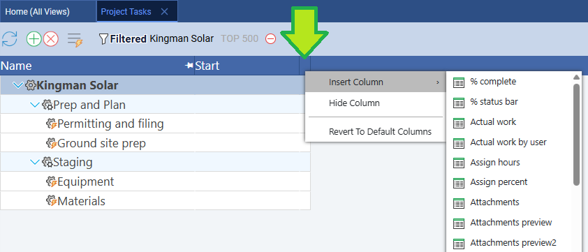
Go to Home → Projects, right-click VR-40 Actuator Manufacturing Line, and choose Admin → Subprojects. Eight top-level stations and sixteen nested subgroups should appear in the exact order and nesting from the CSV. Open the project’s task grid and right-click any column header to add Predecessors, Users, and Duration as visible columns if they are not already shown.
Audit note: count before you move on. The task grid should show 197 rows. The Subprojects admin view should show 16 leaf subgroups under 8 station-level parents. If either count is off, the most common cause is a partial import — reopen the CSV and confirm no row was truncated, then re-run the import; Maverick’s importer updates existing tasks by name rather than duplicating them, so a re-import is safe.
Station 4: Confirm the Dependency Cascade
Because the Predecessors column is a first-class field on every task record, the link relationships arrive already wired — unlike the tagged-paste technique used elsewhere on this site, there is no separate manual-linking protocol here. What is worth doing instead is reviewing which links landed where they matter most. Sort the Gantt by start date and look for two things: the Station 4 step that mates the gearbox subassembly to the motor subassembly, and the Station 5 firmware bring-up that starts before hardware integration is finished.
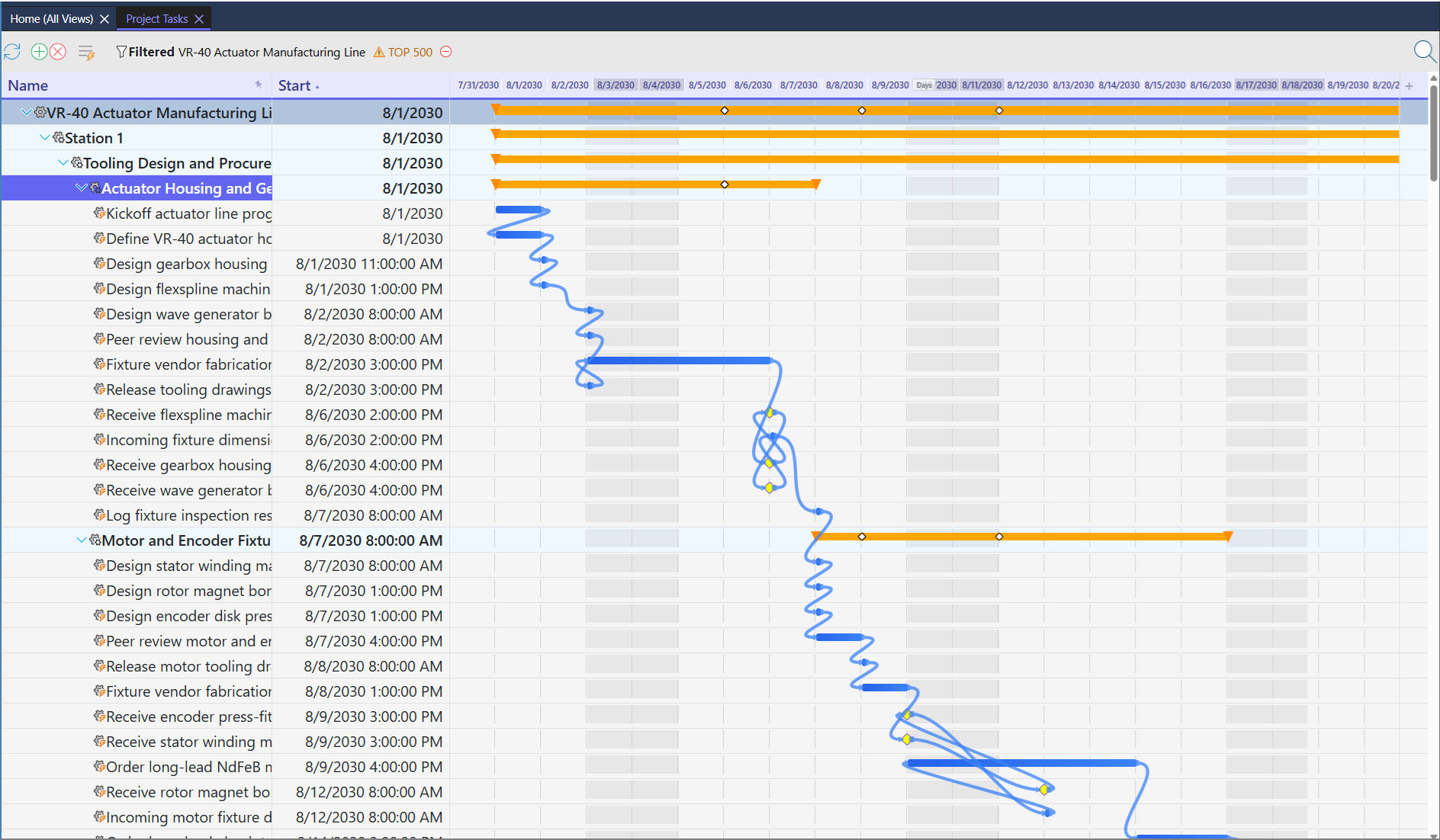
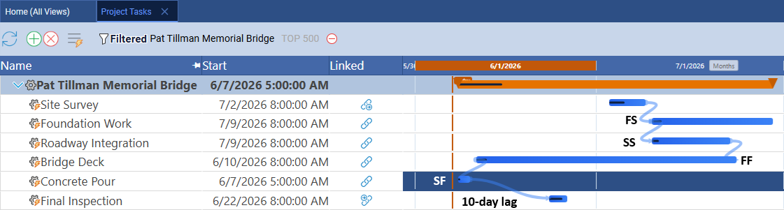
Look for the one Finish-to-Finish convergence on this schedule. “Mate gearbox subassembly to motor subassembly” carries two Finish-to-Finish predecessors — the last machining task in each of Station 3’s two parallel subgroups. That is the exact moment the mechanical and electromechanical build tracks become one physical part. Two rows later, “Flash bootloader onto actuator controller board” uses a Start-to-Start link with a 3-day lag against Station 4’s completion — firmware bring-up does not wait for hardware to fully finish, it starts three days after hardware integration begins, because a controller board can be flashed and unit-tested on a bench well before the actuator it will eventually control is fully assembled.
Fun Fact: The Gearbox Predates the Robot by 70 Years
The strain wave gearing at the heart of the VR-40 — and at the heart of nearly every actuator in nearly every modern humanoid robot — was not invented for robotics at all. C.W. Musser patented the mechanism in 1955 for aerospace and industrial motion control, decades before a humanoid robot joint needed one. What makes it a fit for robot joints is almost accidental: near-zero backlash and gear reduction ratios of 50:1 to 160:1 in a package a fraction of the size and weight of an equivalent planetary gear train — exactly the torque density a robot joint needs when every gram is fighting the actuator’s own inertia.
| Gearbox Type | Typical Reduction Ratio | Backlash | Torque Density |
|---|---|---|---|
| Harmonic drive (strain wave) | 50:1–160:1 | Near zero (arc-minutes) | High |
| Planetary gear train | 3:1–10:1 per stage | Low but nonzero | Moderate |
| Cycloidal drive | 30:1–120:1 | Near zero | High |
| Spur gear train | 3:1–6:1 per stage | Highest | Lowest |
For more on strain wave gearing and how it compares to other reduction mechanisms, see the strain wave gearing reference on Wikipedia.
Station 5: Assign and Verify Resources
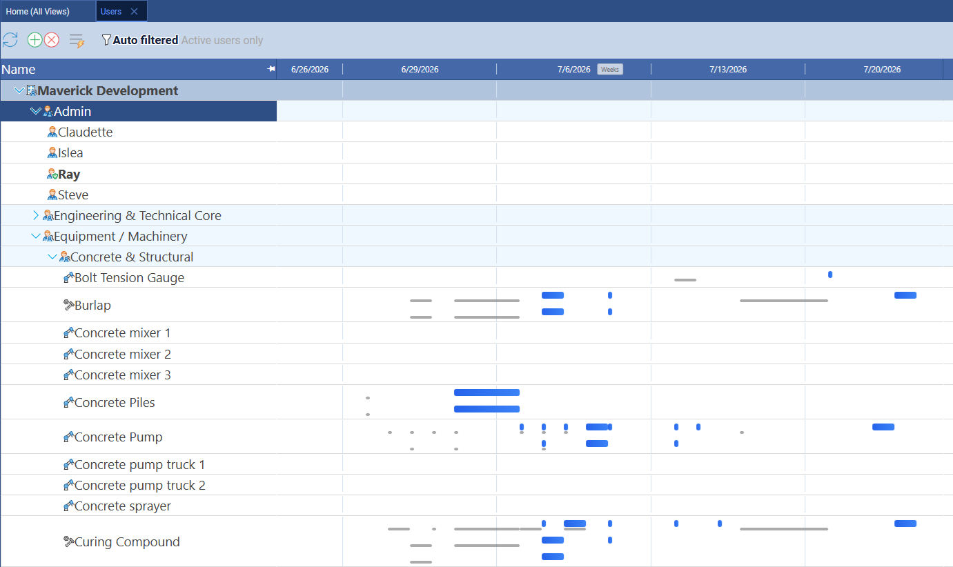
Every task in the CSV already carries its resource assignment from the Users column, so there is no manual assignment step — open the resource pool and confirm the three-type split imported correctly instead.
Then open the resource allocation bar chart to check for over-allocation before setting the baseline.
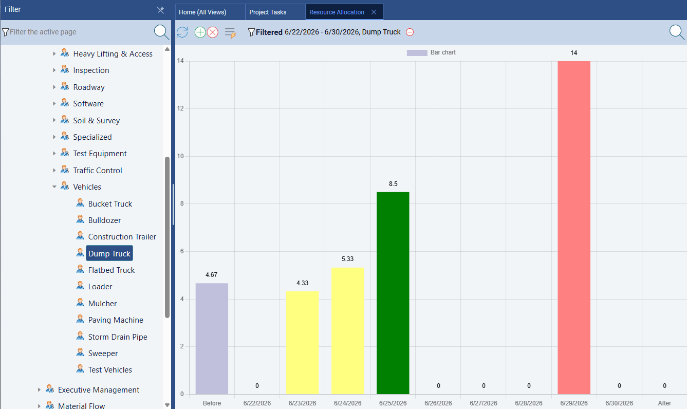
Warning: the CMM and the torque test stand are single-point bottlenecks by design. This CSV assigns the Coordinate Measuring Machine to dimensional inspection tasks in Stations 1, 2, 3, 6, 7, and 8, and the Torque Test Stand to tasks in Stations 2, 3, 4, 5, and 6. That is not an import mistake — a real pilot line typically has one CMM and one torque stand long before it has a second, because both are capital equipment, not headcount. If the allocation chart shows either one over-allocated, the fix is a schedule shift or a second shift on that station, not adding another named resource that does not exist yet on the shop floor.
Station 6: Set the Baseline
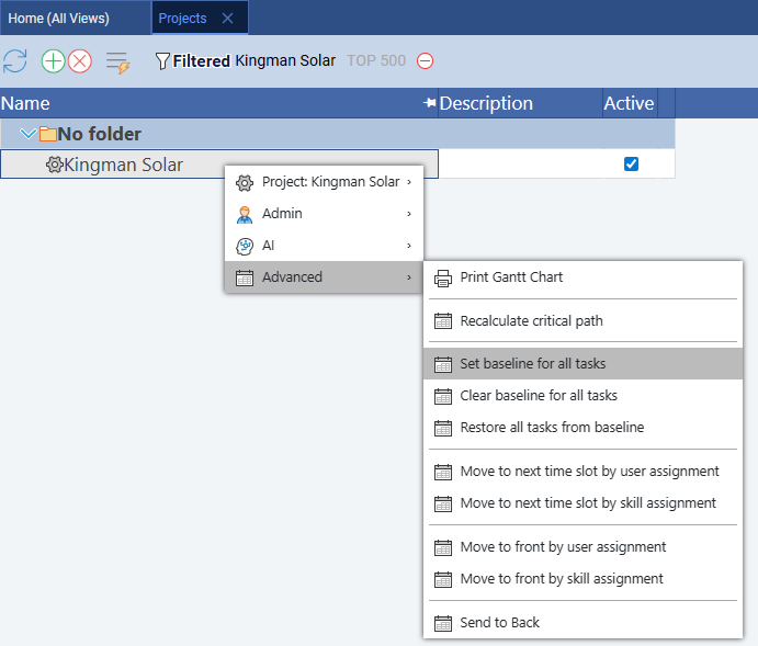
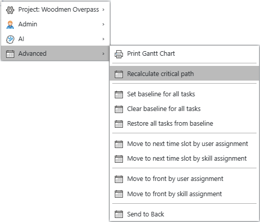
Right-click the project row and choose Advanced → Set baseline for all tasks to lock the plan before the pilot build consumes any tooling or material.
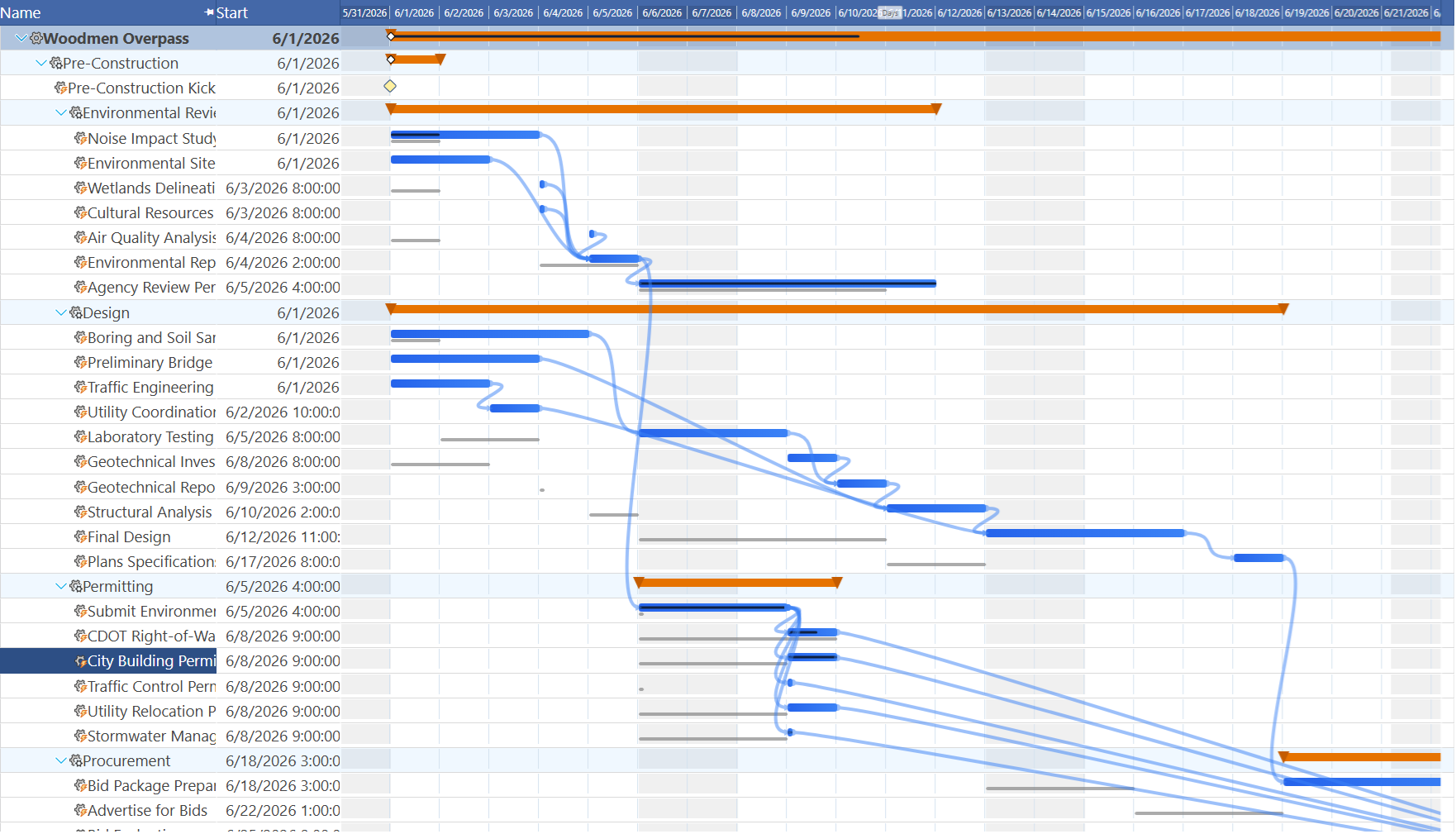
Look for the difference between a tooling ghost bar and a procurement ghost bar. The fixture vendor lead time in Station 1 carries a 15-day ghost bar that is fully within Maverick’s control to renegotiate. The NdFeB magnet second-source qualification in Station 8 carries a 15-day ghost bar too — but rare-earth magnet supply is a global, not a vendor-specific, constraint. When either bar drifts later, the response is different: call the fixture shop for one, start a second supplier conversation months earlier next time for the other.
Station 7: Run the Critical Path
Right-click the project row and choose Advanced → Recalculate critical path. Critical tasks appear in red.
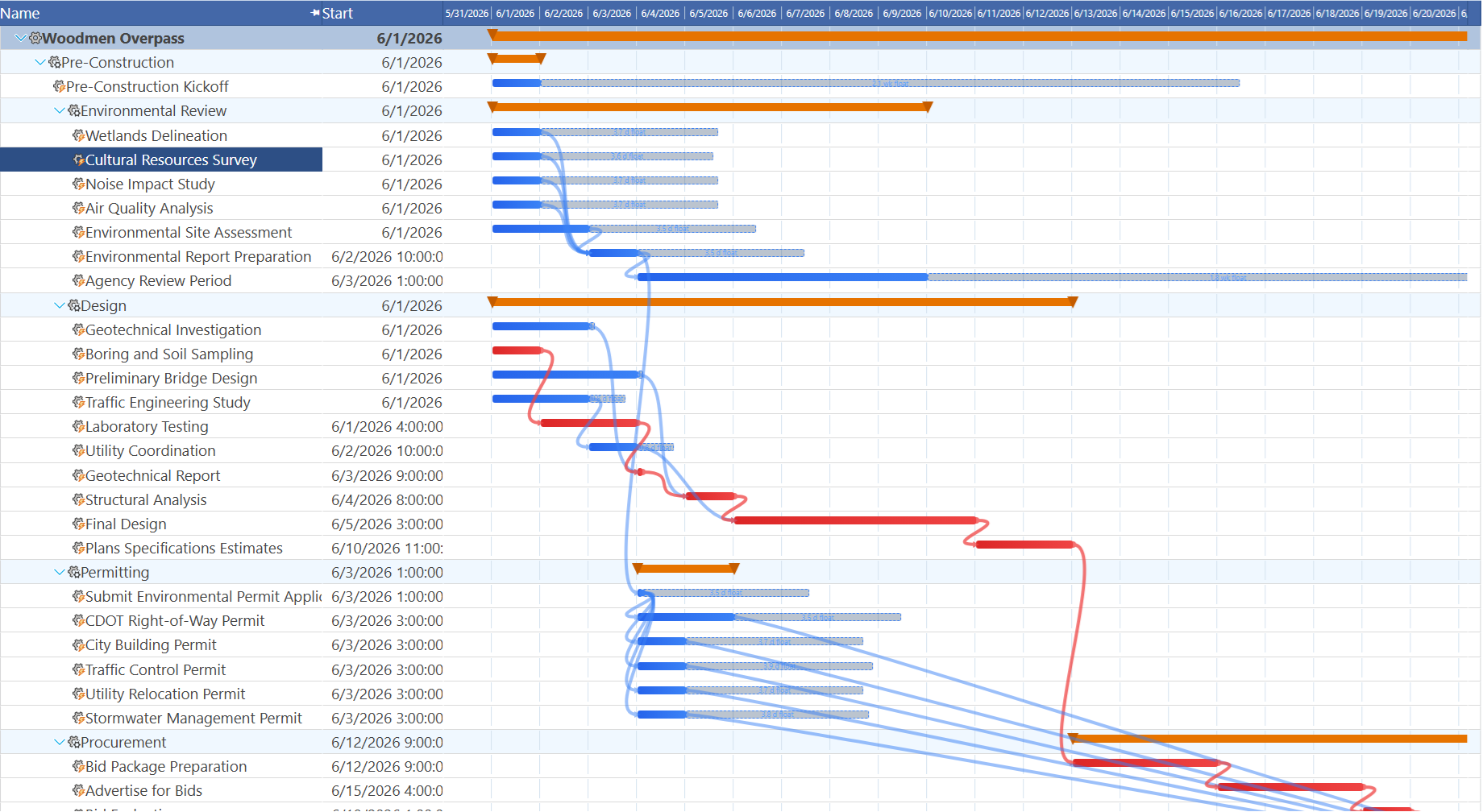
Industry insight: the critical path runs through a quality gate, not a lathe. Machining is the most visually dense part of this schedule — Stations 2 and 3 have more tasks and more machine resources than any other station — but zero float ends up concentrated at the Station 6 first article inspection gate and the Station 8 long-lead magnet second-sourcing task. On a mature production line, cutting metal is rarely what determines the finish date; the gate that decides whether metal that has already been cut is good enough to ship usually is. That is the single biggest lesson this blueprint teaches about ramp scheduling specifically: machining capacity is scalable with a second shift, but a quality gate and a global material constraint are not.
Station 8: Explore the Resource-Centric Gantt
Switch to the resource-centric Gantt to see all three resource types laid out across the full 33-week program.
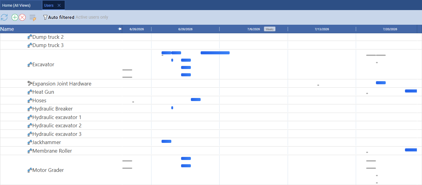
What to look for in the resource Gantt. Material rows — the gear steel, the housing billet, the magnets — should show two distinct clusters: a light one at the Station 1–3 pilot quantities, and a much heavier one at the Station 8 volume-ramp purchase orders. Machine rows should show near-continuous use through Stations 2 and 3, then thin out as work shifts to assembly, controls, and quality in Stations 4 through 6. Human rows tell the ramp story most clearly: the CNC Machinist and Assembly Technician rows should visibly step up in density at Station 7, where second-shift hiring and cross-training land — the schedule's clearest signal that this is a line being built to scale, not a single unit being finished.
Related Topics
For a full explanation of Gantt chart task bars, link lines, and the baseline ghost bars used in Stations 4 and 6, see Gantt Charts in Project Management. For the four link relationship types used in the Predecessors column, see Task Link Relationships Explained. For how Maverick calculates zero-float tasks, see Critical Path Method. For the full workflow of setting, clearing, and restoring baselines, see Project Baselines: Set, Clear, and Restore. For how to read the resource allocation bar chart and resolve the kind of shared-machine bottleneck described in Station 5, see Resource Allocation Bar Chart. To see the same kind of schedule built by pasting a single tagged text block instead, follow the CRISPR-Cas9 Gene Therapy R&D Program blueprint; to see one built entirely by AI prompts, follow the Battery Energy Storage System blueprint.